Process Insights
Understanding Machine Dynamics
Process Implications and Requirements for Successful High-Speed Machining
Dr. Scott Smith, researcher and professor of Mechanical Engineering at the University of North Carolina-Charlotte, spoke at Makino’s Aerospace Seminar in 2000. His topic was “Machine Dynamics: Process Implications and Requirements.” With Dr. Smith’s permission, we’ve reprinted some of the highlights of his presentation here for this edition of Radical Departures.
Determining the Key To Success
In defining high-speed machining, spindle speed alone is not enough, nor is high power, fast motions, tool changes, high performance controllers or advanced tool materials. Clearly, these influencers are important, but the real question that must be asked in creating successful high-speed machining applications is this: “How much of the available speed, and power can be used at the cutting edge or cutter work-piece interface?”
This is not necessarily easy to determine. Current machine tool specifications and literature do not supply the answer. It is also not easy to extrapolate from conventional machining practices. The phenomena in high-speed machining are different than those of conventional machining, and sometimes they are even counter-intuitive. The importance of understanding machine dynamics becomes evident in high-speed machining, then, when we consider their effect on such issues as specialization in machines, matching tools to machines, and optimizing machine usage.
Machine Specialization Is One Factor
One factor in determining the success of a high-speed application has to do with machine specialization. What is meant by machine specialization? Simply put, different operations require different machines. Titanium machining, for instance, occurs mostly in the lower-speed process damping range. For this reason, a lower-speed, higher-torque spindle is preferable for titanium machining applications. Ideal spindles for a titanium application would likely run at speeds less than 5,000 rpm. Aluminum machining, on the other hand, occurs primarily in a much higher speed range. Therefore, a spindle speed exceeding 12,000 rpm is preferable for aluminum machining, even though such a high- speed spindle may have poor low-speed performance.
Smith compares the effects of this specialization to the notable changes in the way athletic shoes have been designed, manufactured, and sold over the years. He calls this idea the Tennis Shoe Analogy: “Tennis shoes used to be inexpensive, and were used to play tennis, in track and field and for basketball. Now, each of these activities has a special purpose shoe. The special purpose shoes perform very well for their specified activity, but perform poorly for the others. Serious competitors need the special purpose shoes in order to compete. Because the new shoes are much more expensive, you cannot afford to misapply them.”
Misapplication of specialized technology can be a costly mistake. One result of the misapplications possible with high-speed machining is chatter. Machine dynamics, Smith argues, become particularly important with regards to chatter. Many high-speed applications are limited by chatter problems. Chatter, which results from insufficient dynamic stiffness, is determined largely by spindle speed and depth of cut.
Figure 1 demonstrates axial depth of cut versus spindle speed for a given radial depth of cut (usually a slot). Shaded areas on the diagram represent chatter. The figures for “a” represent results with a typical end mill. The figures for “b” represent results with a typical large, multi-insert-face mill.
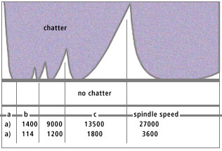 Figure 1.
Know the Possibilities, Respect the Limits
Understanding machine dynamics can spell the difference between successful high-speed machining and less successful attempts. What is most important for machine tool users is that they understand the performance capabilities of each tool on each machine, and utilize their equipment for optimum performance. It is not obvious from the start which tools are best. Four key actions to a better understanding of machine dynamics are: testing the equipment oneself, having outside testing done, maintaining and using a results database, and creating and implementing repeatable setups.
Testing processes are not as tedious as they once were. Smith notes that testing technology is now available commercially in a product called Harmonizer™, from Manufacturing Laboratories, Inc. (MLI). Harmonizer™ is easy to use. All a user would need to enter is spindle speed, maximum allowable speed and number of teeth. That user would then set speeds and cutter teeth, then record cutting into the system. Harmonizer™ works by applying a fundamental rule:
Once finished, the next step is to select a new spindle speed to repeat the process.
Tool Tuning, Another Key Step
Another essential element to machine dynamics is tool tuning, that is, the process of matching tools to machines. Success with this process demands the development of a set of tools specially “tuned” for each machine. This is only possible once the machine user has derived a database of performance information from experiments with the machine. For each tool, the user should be able to deduce a preferable speed and a maximum depth of cut. In examining the data, it will become evident that some lengths are preferable to others and demonstrate a higher metal removing rate (MRR). Some NC programmers have been able to use their experimental database to produce chatter-free parts on the first try.
Using the database for tool tuning requires repeatability. That means it is important that machine users rely on the same tool lengths, same tool holders, and same tightening torques every time. The payoffs of repeatability are a much higher MRR and better overall machine utilization.
What does this mean for machine tool builders? Well, for one thing, customers are becoming increasingly aware of machine performance limitations. They want repeatable machines, and some even want to buy testing information. As users begin to appreciate and use machine dynamics, repeatability will be a real selling point for machine tools. Some features these users will demand include: consistent drawbar forces, repeatable spindles, well-controlled preloads, information on design changes and designs that are adaptable to applications.
Implications of Machine Dynamics
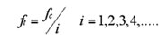
It is important to note that sometimes lower drawbar forces are preferable to higher ones. Higher drawbar forces stiffen the tool-spindle connection, increasing static stiffness. This is demonstrated in Figure 2. Higher drawbar forces also decrease damping in the tool-spindle connection, as shown in Figures 3 and 4. Achievable MRR depends in equal part on stiffness and on damping. According to Smith’s findings, higher drawbar force reduces damping more than it increases stiffness in joints.
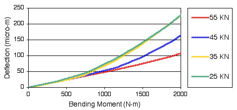 Figure 2.
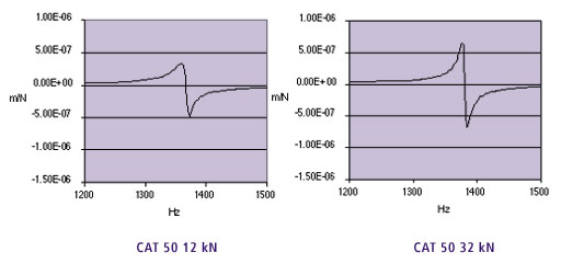 Figures 3 and 4.
Faster is not always better. As far as the issue of spindle speed goes, tool tuning often reveals that, even with tool tuning, it is often necessary to use tools at speeds significantly lower than the maximum achievable speed. For example, when spindle modes dominate, the tuning effect is not as strong. Moreover, many tools prefer speeds lower than the maximum spindle speed. These findings indicate that it would be preferable to design a spindle with a specific tool in mind, then place the stable zone.
This, in turn, creates additional implications inherent for tool holders. A tool-specific spindle would mean no tool holder is required. Rather, the tool might be held, for instance, directly in the spindle with a shrink-fit connection without a tool holder. This tool-specific spindle operation would eliminate all the myriad difficulties currently associated with making a tool holder suitable for high-speed operations, including issues with repeatability and fit, problems maintaining contact and balance and tolerance concerns. Regrinding the taper would also not be necessary with a tool-specific spindle setup. These improvements simplify setup and procedure.
Likewise, if no tool holder is required, then no drawbar is required either. With no drawbar, there would be no need for a long stack of Belleville washers, no need to be concerned with repeatable drawbar force and no more balance issues for drawbar stack. Spindle length could be reduced, freeing up internal space in the machine. This leads to easier through-spindle coolant.
The benefits to tool-specific spindle manufacture do not end there. Preload mechanisms would also be much simpler to conduct. Since a single tool runs best at a particular speed, then the spindle can, in turn, be designed to run at top speed. Spindles could have a clearance at low speed and achieve full preload only at operating speed.
There are even more benefits to the use of tool-specific spindles. If designed to be tool- specific, spindles would become less expensive. Multiple tool-specific spindles could exist on the same machine. Finally, NC programming would be simplified by the single high speed.
Clearly, it is evident that there are many benefits to be realized by the proper understanding and utilization of machine dynamics. The most important step in getting there, however, is to understand your machine. Know what it can do, and how it best performs. This knowledge can only be gleaned by testing, retesting, and more testing. Tool tuning is a valuable resource for maximizing machine potential. Keep accurate databases of your findings, and strive for repeatability in each test. If you follow this advice, successful optimization with high-speed machining techniques will be well within your reach.
If you’re interested in learning more about Dr. Smith’s views on machine dynamics, read the Radical Departures article “UNC-Charlotte Researchers Focus on High Speed: Getting the Most From Your Machines.”